DIGICORP CIVIL Design è un applicativo di Autodesk AutoCAD e Bricsys BricsCAD per la progettazione e contabilizzazione di opere civili sul territorio: indispensabile per i tecnici.

DIGICORP CIVIL Design è un applicativo di Autodesk AutoCAD e Bricsys BricsCAD per la progettazione e contabilizzazione di opere civili sul territorio: indispensabile per i tecnici.
Prova subitoChe cos'è CIVIL Design?
Le tipologie di interventi sul territorio sono molteplici: CIVIL Design offre diverse configurazioni, chiamate "soluzioni", tagliate su misura per affrontare diversi temi di progettazione.
Puoi avere a disposizione le funzioni di CIVIL Design grazie al software CAD&Pillar che ha già integrato il motore OEM compatibile con AutoCAD 2026.
La nuova release 15 è ora disponibile!
Progettare disegnando, ora anche BIM, oltre ogni ostacolo.
Scopri di piùBacini Idrografici
E' la soluzione di CIVIL Design per lo studio idrologico-idraulico dei bacini idrografici.
Acquedotti
E' la soluzione per progettare, calcolare e verificare reti in pressione direttamente in ambiente AutoCAD. Ti permette di interfacciarto il motore di calcolo EPANET.

Fognature e reti di drenaggio
E' la soluzione che aiuta a gestire le reti di fognatura e di drenaggio
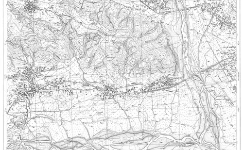
Raster
La soluzione Raster è stata studiata per permettere ai clienti di CIVIL Design di potenziare la gestione delle immagini raster in AutoCAD. Nei progetti di opere sul territorio, infatti, c'è sempre la necessità di utilizzare cartografie raster, come Carta Tecnica Regionale, ortofoto, foto satellitari o mappe catastali.
Sezioni Contabili
È la soluzione di CIVIL Design che permette di disegnare sezioni di computo, vestirle e calcolare le aree e i volumi. Strumento indispensabile per la progettazione e per la gestione la contabilità di movimenti di materia.
Profili
È la soluzione che comprende tutte le funzioni necessarie a progettare e disegnare profili di qualsiasi tipo di opera. Grazie alla flessibilità ed alla possibilità di gestire un numero illimitato di polilinee e sezioni, è pertanto utilizzabile per profili di fognature, acquedotti, linee tecnologiche in genere.
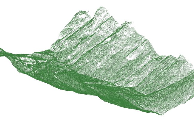
Nuvole Punti
È l'insieme delle funzionalità presenti in tutte le soluzioni di CIVIL Design che permettono di usare in AutoCAD le nuvole di punti laserscan.
Requisiti di sistema
I requisiti software e hardware sono gli stessi della versione full di Autodesk AutoCAD© o Bricsys BricsCAD per i sistemi operativi da essi supportati.

Non hai AutoCAD o BricsCAD?
Puoi avere a disposizione le funzioni di CIVIL Design grazie al software CAD&Pillar 11.0 che ha già integrato il motore OEM compatibile con AutoCAD 2026.
Digicorp Ingegneria s.r.l. You Tube Channel
Produzione e vendita di software per la progettazione e contabilizzazione di infrastrutture (strade, ferrovie, opere idrauliche, topografia). Servizi tecnici di progettazione e consulenza.
GuardaFAQ
Hai bisogno di aiuto?
Se hai domande riguardo al software, non esitare a contattarci. Vorremmo aiutarti senza esitazione.
Lunedì - Venerdì :
08:30-13:00 e 14:30-18:00
tel:
0432 511556